

Transient heat conduction
1 Errata
Section titled “1 Errata”-
Slide 10 gives as the lumped-capacitance criterion. Use the usual engineering criterion
A Biot number below one alone does not ensure negligible internal temperature differences.
2 Reading list
Section titled “2 Reading list”- Çengel and Ghajar (2015), sections 4.1 to 4.3, for transient conduction models.
- Bird et al. (2006) for energy balances.
3 Choose a transient-heat model
Section titled “3 Choose a transient-heat model”| Given conditions | Model and checks |
|---|---|
| Nearly uniform interior temperature | Test , then use the lumped balance, Eq. 1. |
| Finite wall, cylinder or sphere with significant internal gradients | Use the matching finite-body series; specify half-thickness or radius and the surface film condition. |
| One-term finite-body approximation | Check Fourier number and the error from omitted terms before using Eq. 18 or its radial counterpart. |
| Early change near one face; remote boundary undisturbed | Use the semi-infinite solution with the actual surface condition; compare penetration depth with body thickness. |
4 Lumped capacitance approach
Section titled “4 Lumped capacitance approach”4.1 Balance and integration
Section titled “4.1 Balance and integration”If internal conduction resistance is small compared with the surface film resistance, internal temperature differences are small. The body has one temperature and thermal capacitance in joules per kelvin. is volume in and is the surface area through which heat transfers, in . With outward heat positive, the balance is
Both sides have units of watts. A hot body has a negative , while a body colder than the fluid heats with the same equation. Define excess temperature and initial excess , both in kelvin. Because is constant, . Separating variables in Eq. 1 gives
For heating as well as cooling, integrate using . The ratio is positive, and hence
The integrated balance then gives
The time constant is in seconds. Thermal resistance in kelvin per watt times thermal capacitance gives this same time constant. Inverting Eq. 3 yields
After one time constant the excess is 36.8% of its initial value; after three it is 5.0%, and after five it is 0.67%. Increasing density, volume or specific heat slows the response; increasing exposed area or speeds it up.
A lumped body cools with constant properties and constant surroundings. After one time constant, what fraction of its initial excess temperature remains?
Explanation
For lumped cooling, the fraction of the initial temperature difference remaining is
After one time constant,
About 36.8 percent remains. The body has completed about 63.2 percent of its temperature change.
4.2 Energy transferred
Section titled “4.2 Energy transferred”The instantaneous outward rate is in watts. Integrating Eq. 4 gives the outward transferred energy in joules,
is the integration time in seconds. At long times the limiting signed energy is . During heating both and are negative under the outward convention. Their ratio is positive. The source deck calls this cumulative energy , and sometimes uses for a rate. We use , and consistently with topic 1, where is flux in .
4.3 Checking the lumped assumption
Section titled “4.3 Checking the lumped assumption”The conduction-to-convection resistance ratio for a wall is
For the lumped test, use exposed area and
The corresponding Biot number is
Use . For a two-sided wall of thickness , ; for a long cylinder ; for a sphere .
The Biot number indicates which resistance controls the transient response:
- For , internal conduction resistance is small compared with surface convection resistance. Heat redistributes within the solid fast enough for its temperature to remain nearly uniform. The lumped model represents the solid by a single temperature that changes with time.
- For , both resistances matter. Internal temperature gradients must be resolved with a spatial conduction model and a convective boundary condition.
- For , internal conduction resistance dominates. The surface approaches the surrounding fluid temperature while the interior responds more slowly. A prescribed surface temperature equal to the fluid temperature can then be a useful approximation; the lumped model is unsuitable.
These limits are approximate, and the numerical Biot number depends on the chosen characteristic length. A large Biot number alone does not specify how much cooling has occurred, because elapsed time also matters.
Keep the two length conventions separate. The lumped test uses . Finite-body series and Heisler charts use wall half-thickness or cylinder and sphere radius in both Biot and Fourier numbers. For a sphere, the chart Biot number is three times the lumped-test value. The in the definition is the solid conductivity, written elsewhere in these notes.
For example, the steel sphere below has , so its lumped cooling model is appropriate. Using its diameter instead of would multiply this test value by six. That length error can change a model choice for a body closer to the criterion.
A sphere has radius m, solid conductivity and . Using , what does the usual Biot test suggest?
Explanation
For a sphere,
Thus,
Since the Biot number is below 0.1, the lumped model can be used.
For this test, use volume divided by exposed surface area, which is one third of the sphere’s radius. The finite-sphere charts use the radius itself to define their Biot number. Use the length specified by the model you are checking.
4.4 Fourier number
Section titled “4.4 Fourier number”The Fourier number indicates how far a temperature disturbance has diffused:
- For , the diffusion distance is small compared with . A semi-infinite solid can describe early surface changes if distant boundaries have little influence.
- For , diffusion has acted over distances comparable to . Finite geometry and the other boundaries affect the response.
- For , diffusion has acted across the body. This alone does not establish equilibrium with the fluid, since surface convection may still limit the rate of heating or cooling.
Thermal diffusivity is in . For the lumped length define
Combining the definitions of Biot number, Fourier number and time constant gives
Thus Eq. 4 is
The conductivity cancels from the product. Once internal gradients are negligible, improving conductivity does not change the lumped cooling rate. Fourier number compares elapsed time with a diffusion time. Its numerical value depends on the chosen length.
For a lumped body the remaining temperature excess depends on , as shown above. A large Fourier number can coexist with little temperature change when the Biot number is very small.
Fourier number also helps choose a finite-body approximation. For the uniform-initial-temperature, constant-convection problems below, the one-term series approximation is normally used for . At earlier times retain enough terms or check whether a semi-infinite model is suitable. This criterion belongs to these solutions, not every diffusion problem.
For example, let a wall be thick, cooled equally on both faces, with . After , its half-thickness is and . The one-term wall approximation meets the stated time criterion. Using the full thickness gives and suggests a different approximation. Use elapsed time since the boundary condition changed, in seconds, and the same half-thickness in both and .
4.5 Classroom example 1: steel sphere
Section titled “4.5 Classroom example 1: steel sphere”Cooling a steel sphere
Section titled “Cooling a steel sphere”A hot spherical particle made out of carbon steel (1.25 cm diameter, , ) is cooled by a fan, with convection coefficient of and air temperature of . How long would it take for the sphere to reach a temperature of ?
Worked solution

Data
| Quantity | Value |
|---|---|
| Diameter | |
| Initial temperature | |
| Target temperature | |
| Air temperature | |
| Heat transfer coefficient | |
| Steel conductivity | |
| Steel density | |
| Steel specific heat capacity |
The original slide does not supply density or specific heat capacity. These two values come from the lecturer’s notes.
Assumptions
- Uniform initial temperature.
- Constant material properties and heat transfer coefficient.
- Constant air temperature.
- Radiation and heat transfer through supports are neglected.
- No internal heat generation.
Calculations
First test whether conduction within the sphere is fast enough to keep its internal temperature nearly uniform. For a sphere,
The Biot number compares internal conduction resistance with the surface convection resistance:
Since , the lumped model is appropriate. The energy balance is
Its time constant is
Integrating the balance, as in Eq. 3, gives the time to the requested temperature:
Substituting the temperatures and time constant gives
The required excess-temperature ratio is , between and . A time between one and two time constants is therefore consistent with the result. Radiation would increase heat loss, particularly at the initial high temperature, so the result applies to convection alone.
Answer
The sphere reaches after approximately , or , in the convection-only model.
4.6 Classroom example 2: brass quench bath
Section titled “4.6 Classroom example 2: brass quench bath”Quenching brass spheres in water
Section titled “Quenching brass spheres in water”In a manufacturing facility, 5 cm diameter brass spheres (, , ) initially at are quenched in a water bath at for a period of 2 minutes at a rate of 120 spheres per minute. If the convection heat transfer coefficient , determine:
- The temperature of the spheres after quenching
- The rate at which heat needs to be removed from the water in order to keep its temperature constant at .
Worked solution
Data
| Quantity | Value |
|---|---|
| Sphere diameter | |
| Brass conductivity | |
| Brass density | |
| Specific heat capacity | |
| Initial temperature | |
| Bath temperature | |
| Residence time | |
| Heat transfer coefficient | |
| Sphere throughput |
Assumptions
- Uniform initial temperature in each sphere.
- Constant material properties and heat transfer coefficient.
- Uniform bath temperature, maintained at .
- No internal heat generation.
- Heat transfer from the bath to other surroundings is neglected.
- Steady throughput for the bath heat-duty calculation.
Calculations
The characteristic length for a sphere is
Test the internal temperature gradients using
This is below 0.1, so each sphere can be treated as a lumped thermal capacitance. Its time constant is
The integrated energy balance gives
After two minutes,
Now calculate the heat released by one sphere. Its volume and mass are
The decrease in its stored thermal energy is
At steady throughput, the cooling equipment must remove heat at the same average rate as the spheres release it to the bath:
The exit temperature lies between the bath temperature and the initial sphere temperature, as required. There are 240 spheres in the bath at steady operation, but heat duty depends on the throughput of two spheres per second. Inventory determines how many spheres are cooling at once.
Answer
The spheres leave at approximately . The required heat-removal rate is .
5 Non-lumped capacitance approach: finite medium
Section titled “5 Non-lumped capacitance approach: finite medium”5.1 Plane-wall problem
Section titled “5.1 Plane-wall problem”If exceeds the acceptable lumped range, retain a spatial temperature profile. A large plane wall has thickness , with the mid-plane at and a surface at . Both faces see the same constant and . Width and height are large relative to thickness so edge losses can be neglected. Uniform initial temperature and the material assumptions above make the problem linear and symmetric. The equation is
Symmetry supplies at . At , the surface stores no energy, so conduction arriving there equals outward convection,
Initially throughout . These are two boundary conditions for the second spatial derivative and one initial condition for the first time derivative. An insulated face has the same zero-gradient condition as a symmetry plane. With prescribed surface temperature, replace Eq. 12 by , the infinite- limit.
A plane wall starts uniformly hot and cools identically from both faces. Which condition holds at its midplane?
Explanation
Both faces cool in the same way, so the temperature distribution is symmetric about the midplane. There,
No heat crosses the midplane. Its temperature can still fall as heat leaves through the two outer faces.
5.2 Non-dimensionalisation and series solution
Section titled “5.2 Non-dimensionalisation and series solution”The source reuses for a dimensionless temperature and for Fourier number. Here retain in kelvin and in seconds. Define a dimensionless excess , position and finite-wall Fourier number separately,
The dimensionless position is
The finite-wall Fourier number is
The chain rule gives
and
Substituting in Eq. 11 cancels the common property and temperature factors, giving
The conditions become
Here . This Biot number uses the wall half-thickness. For cylinders and spheres the series uses , not . Keep this length distinction when using tables or charts.
Seek . Substitution in Eq. 14 gives
A negative separation constant gives decay toward equilibrium. Then is proportional to and
Symmetry sets . The surface condition sets the dimensionless eigenvalues,
Each positive root supplies a mode. Linearity permits their sum, and the uniform initial condition fixes the coefficients,
Orthogonality on makes the coefficient of one mode equal to the integral of that mode divided by its squared norm. The numerator is
and the denominator is
Therefore
Symmetry removed the sine term, the convection boundary determined the roots, and the initial condition determined . At small Biot number the first root tends to zero and the profile flattens. At infinite Biot number the first wall root tends to .
5.3 One-term approximation and coefficients
Section titled “5.3 One-term approximation and coefficients”Higher roots decay more rapidly because their squares multiply time in Eq. 16. For , the usual one-term approximation is
is the mid-plane dimensionless excess. At earlier times use more series terms, or a semi-infinite solution only if its own far-boundary test holds. The range between early semi-infinite behaviour and the one-term range is not automatically covered by either approximation.
The wall, cylinder and sphere have different radial operators and boundary conditions. Each geometry therefore has its own roots and coefficients. For a long cylinder, the eigenvalue relation is
For a sphere, the eigenvalue relation is
Both radial solutions use . and are Bessel functions of the first kind, of orders zero and one. They arise from the cylindrical radial Laplacian. Their arguments, the roots , and coefficients are dimensionless. The first coefficients for these geometries are
Compute the first root numerically or interpolate the appropriate textbook table. As grows, the first roots approach for a wall, 2.4048 for a cylinder, and for a sphere. At small , and approaches , and , respectively. The geometry factors recover the lumped exponent based on .
A finite wall has Fourier number , based on half-thickness. What is the best next step before using the one-term solution?
Explanation
The usual condition for the one-term approximation is
Here the Fourier number is only 0.05. Keep more terms, or check whether a semi-infinite model is suitable at this early time. Use the half-thickness throughout. A small Fourier number alone does not justify the lumped model; that requires a Biot-number check.
5.4 Deriving the wall’s transferred-energy fraction
Section titled “5.4 Deriving the wall’s transferred-energy fraction”Integrate the one-term profile across the half-thickness:
The released-energy fraction follows from the decrease in stored energy:
Here
A position chart gives , so multiply by the centre ratio before finding temperature.
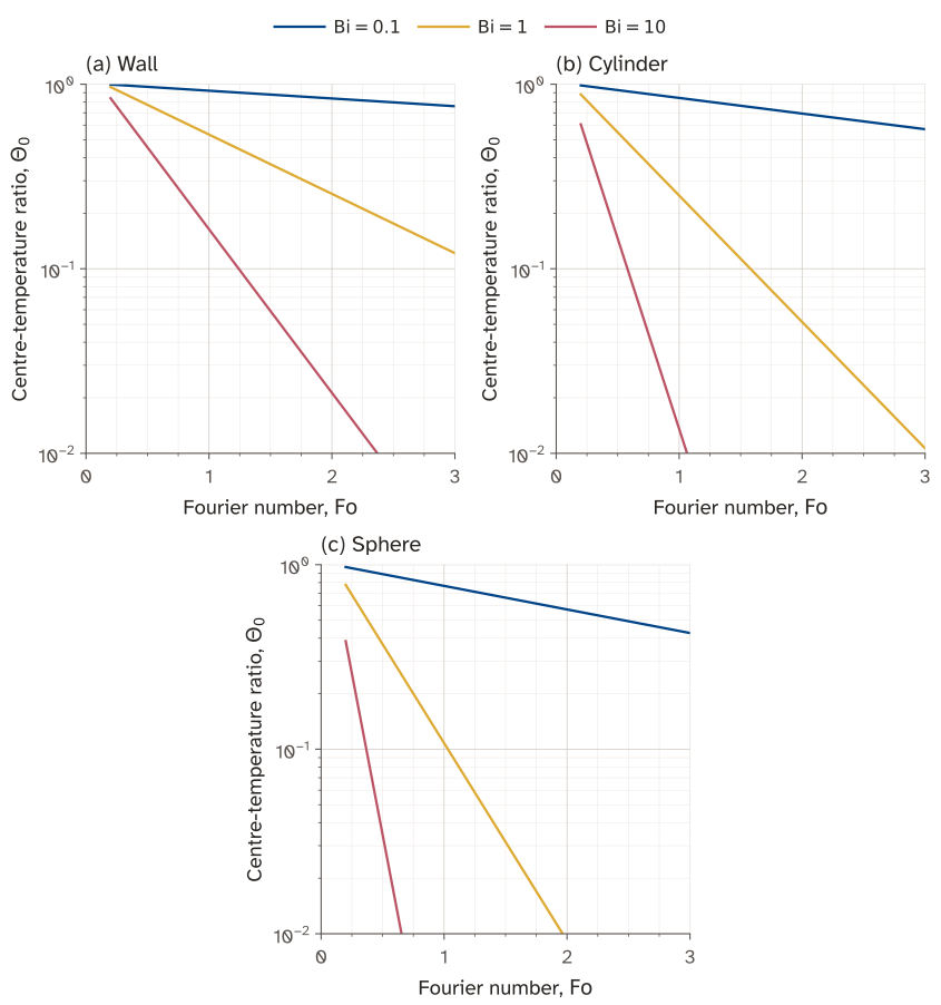
The one-term curves start at .
5.5 Cylinder and sphere solutions and charts
Section titled “5.5 Cylinder and sphere solutions and charts”The one-term cylinder and sphere solutions share the centre time factor in Eq. 18, but use and their own roots and coefficients. With , their position functions are
At the centre use the limit , avoiding division by zero. Every shape function equals one at its centre and has zero centre gradient. The cylinder is long enough for end losses to be negligible. A short cylinder needs both axial and radial factors, as in classroom example 4.
The centre charts on source slides 23 and 25 use the same logarithmic excess axis and curve labels as the wall chart. Source slides 24 and 26 show position ratios and cumulative-energy fractions. Their computed replacements are Figure 3 and Figure 4, with the heat fractions obtained from volume averages,
Use
for each geometry. For the same geometry length, Biot and Fourier numbers, a sphere responds faster than a cylinder, which responds faster than a wall. Their surface area per volume increases in that order. These comparisons need matching dimensionless groups; size or chart-axis limits alone do not establish a universal ranking.
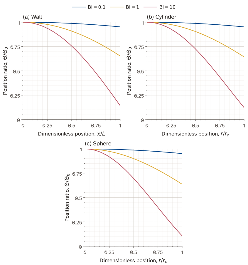
The horizontal coordinate is for the wall and for the cylinder and sphere. Multiply the plotted position ratio by .
5.6 Classroom example 3: insulated brick wall
Section titled “5.6 Classroom example 3: insulated brick wall”Cooling an insulated brick wall
Section titled “Cooling an insulated brick wall”A flat wall of fire-clay brick (0.5 m thick) initially has a uniform temperature of 200 K. One of its faces is suddenly exposed to hot gas at 1200 K. If the heat transfer coefficient on the hot side is and the other face of the wall is insulated, determine:
- The time it takes for the centre of the wall to reach 600 K
- The temperature of the insulated wall at the time evaluated in (a)
Properties of fire-clay brick:
Worked solution
The insulated face has zero normal temperature gradient. Reflecting the brick about that face produces a symmetric wall heated from both sides.

Data
| Quantity | Value |
|---|---|
| Real brick thickness | |
| Initial temperature | |
| Gas temperature | |
| Heat transfer coefficient | |
| Brick conductivity | |
| Brick density | |
| Specific heat capacity | |
| Reflected-wall half-thickness | |
| Physical brick-centre position | , |
| Target temperature at the brick centre |
Measure position from the insulated face. Reflection makes that face the midplane of the equivalent wall.
Assumptions
- Uniform initial temperature.
- Unidirectional conduction normal to the wall.
- Perfect insulation at the rear face.
- Constant material properties, gas temperature and heat transfer coefficient.
- No internal heat generation.
- Radiation is neglected.
Calculations
The insulated face obeys , which is the symmetry condition of the finite-wall solution. First calculate the diffusivity:
The wall Biot number is
For this one-sided wall, also. The Biot number is well above 0.1, so a spatial temperature profile is needed. The one-term wall solution from Eq. 18 is
The eigenvalue relation Eq. 15, , gives . Substituting that root into the coefficient relation gives
At the real brick centre, the requested temperature corresponds to
The value applies at the physical centre of the brick, or . The reference position for the symmetric wall solution is , at the insulated face. This is the centre of the equivalent reflected wall, so it is a different location from the physical centre of the brick.
At , the cosine factor is one and the one-term solution gives . At the physical brick centre, it therefore gives . Divide by this cosine factor to find the dimensionless temperature at the insulated face:
Thus and are dimensionless temperatures at different positions at the same time. The value is the insulated-face reference value needed to find the elapsed time.
Use
to find the elapsed time:
Since , the one-term approximation is appropriate. Convert this dimensionless time to seconds:
At the insulated face, and the cosine factor is one. Its temperature is
The insulated face is colder than the brick centre because heat enters from the opposite face. The ordering is consistent with one-sided heating. Constant properties over this temperature range are an idealisation of the classroom model.
Answer
The brick centre reaches after approximately . At that time, the insulated face is at .
5.7 Classroom example 4: short steel cylinder
Section titled “5.7 Classroom example 4: short steel cylinder”Cooling a short steel cylinder
Section titled “Cooling a short steel cylinder”A steel cylinder (, ) is initially at 645 K. It is immersed in an oil bath with a constant temperature of 310K. If the convection heat transfer coefficient at the steel surface is , determine the temperatures at the following locations:
- at the centre of the cylinder after 1 hour?
- at the centre of the top surface of the cylinder?
Properties of steel:
Worked solution
An axial section identifies the two requested points and the two directions of conduction.

Data
| Quantity | Value |
|---|---|
| Cylinder diameter | |
| Full cylinder length | |
| Half-length for the plane-wall factor | |
| Cylinder radius | |
| Initial temperature | |
| Oil temperature | |
| Heat transfer coefficient | |
| Steel conductivity | |
| Steel density | |
| Specific heat capacity | |
| Time for both requested temperatures |
Assumptions
- Uniform initial temperature.
- Axisymmetric conduction in both radial and axial directions.
- Constant material properties.
- Constant oil temperature and uniform heat transfer coefficient on all surfaces.
- No internal heat generation.
- Radiation is neglected.
Calculations
The ends cannot be neglected because the length is only twice the diameter. For a constant-property body with these separable boundary conditions, the short-cylinder excess-temperature ratio is the product of a wall factor and a long-cylinder factor:
Here is the axial midplane and is the axis. The product solves
because each factor solves its own one-dimensional diffusion equation. The diffusivity is
Each factor needs its own Biot and Fourier numbers. For the wall factor,
For the cylindrical factor,
Both Fourier numbers exceed 0.2. Solving and
gives and . The corresponding coefficient relations, Eq. 17 and Eq. 21, give and .
The wall centre factor is
The cylinder centre factor is
At the body centre, both position factors are one. The product and resulting temperature are
At the centre of the top face, and . The wall factor includes , while the radial position factor remains one:
Convert the product to temperature:
The face centre is cooler than the body centre and both temperatures remain between the initial and bath temperatures. A position chart supplies a ratio relative to its own centre value. Multiplying a position ratio alone by the other centre factor would omit part of the cooling history.
Answer
After one hour, the body centre is at approximately and the centre of the top face is at approximately .
5.8 Classroom example 5: egg model
Section titled “5.8 Classroom example 5: egg model”Heating an egg
Section titled “Heating an egg”An egg, initially at a uniform temperature of , is dropped into boiling water at . Taking the convection heat transfer coefficient to be , and approximating the egg to be a 5-cm diameter sphere, determine how long it will take for the centre of the egg to reach .
Worked solution
Data
| Quantity | Value |
|---|---|
| Model sphere diameter | |
| Initial temperature | |
| Target centre temperature | |
| Water temperature | |
| Heat transfer coefficient | |
| Conductivity | |
| Thermal diffusivity |
The conductivity and diffusivity come from the lecturer’s notes.
Assumptions
- Homogeneous spherical body with a uniform initial temperature.
- Radial conduction.
- Constant properties and heat transfer coefficient.
- Constant water temperature.
- No internal heat generation.
- Shell resistance and energy changes due to cooking are neglected.
Calculations
Test lumped capacitance using :
The large Biot number rules out a uniform internal temperature. The sphere solution uses the radius instead:
At the centre, the one-term solution is
Its target value is
The sphere eigenvalue relation Eq. 20 is . With , its first root is . The corresponding coefficient is
Rearrange the centre-temperature relation to find the Fourier number:
This just exceeds 0.2, so the usual one-term criterion is satisfied. The time is
A chart reading of gives about 13.8 minutes, consistent with this estimate. The large Biot number means that internal conduction limits the response. Increasing the external coefficient has less effect than it would in a lumped body. Real eggs have a nonspherical shape and different internal regions, so the calculation is an idealised heating estimate.
Answer
The centre reaches after approximately in the spherical, constant-property model.
6 Non-lumped capacitance approach: semi-infinite medium
Section titled “6 Non-lumped capacitance approach: semi-infinite medium”6.1 Model and boundary conditions
Section titled “6.1 Model and boundary conditions”A semi-infinite solid occupies , with measured inward from a plane surface. Its far field remains at the initial temperature over the time of interest. A finite body can use this approximation while the penetration distance is small relative to the distance to an influential far boundary. A practical guide is , followed by a check that the far boundary’s temperature change is acceptably small. This is a time-dependent condition, rather than a definition of a thick body.
The equation is still Eq. 11, with and . Choose one surface condition. A prescribed-temperature surface has . Alternatively, a surface exposed to fluid has
The sign differs from Eq. 12 because now points inward. For a prescribed-temperature problem, is known. For a convection problem, is an unknown surface temperature determined by the flux balance. Choose the condition that matches the supplied information.
6.2 Error-function solution
Section titled “6.2 Error-function solution”Define the dimensionless depth
This combines depth with the diffusion distance because the ideal body has no finite geometrical length. For a suddenly imposed constant ,
The complementary error function is
Here is a dimensionless integration variable. At the surface gives . At great depth erfc tends to zero and gives . A similarity substitution into Eq. 11 gives . Integration gives proportional to ; the surface and far-field values fix the normalisation in Eq. 32.
For convection, put
The fraction of the possible temperature change is
is a Biot number based on the growing penetration distance. Finite reduces the temperature change through the positive correction . In the infinite- limit the correction tends to zero and Eq. 31 follows with . Evaluate the correction or its relative size when deciding whether to neglect it. For example, at the surface and , the correction is about 0.255. The prescribed-temperature approximation would therefore overpredict the fractional surface temperature change by 0.255 at that instant. For large arguments a scaled complementary error function avoids overflow when evaluating the exponential times erfc.
For the same semi-infinite solid and prescribed surface-temperature step, how does the depth of a fixed fractional temperature change vary when time increases by a factor of four?
Explanation
For the same fractional temperature change, the similarity variable stays constant:
With diffusivity unchanged,
The depth doubles. The semi-infinite approximation must still be valid at the later time.
6.3 Evaluating the semi-infinite solution
Section titled “6.3 Evaluating the semi-infinite solution”
The curves evaluate Eq. 33 and Eq. 31. For comparison, , and .
6.4 Classroom example 6: soil frost depth
Section titled “6.4 Classroom example 6: soil frost depth”Soil frost depth
Section titled “Soil frost depth”What minimum burial depth would you recommend to avoid freezing under conditions for which the soil, initially at a uniform temperature of , is subjected to a constant surface temperature of for 3 months?
Properties of soil:
Worked solution
Measure depth downwards from the cold ground surface. The pipe must lie below the calculated zero-degree isotherm.

Data
| Quantity | Value |
|---|---|
| Initial soil temperature | |
| Prescribed surface temperature | |
| Temperature at the required depth | |
| Elapsed time | |
| Soil conductivity | |
| Soil density | |
| Specific heat capacity |
For this calculation, take three months as 90 days.
Assumptions
- Uniform initial soil temperature.
- Unidirectional conduction normal to a plane ground surface.
- Semi-infinite soil depth over the time considered.
- Constant thermal properties.
- Constant prescribed surface temperature.
- No internal heat generation.
- Soil moisture phase change is neglected.
Calculations
The surface temperature is supplied directly, so use the prescribed-temperature semi-infinite solution rather than a convection boundary condition. The thermal diffusivity is
Convert the duration to seconds:
The diffusion distance provides a useful estimate before solving for depth:
The temperature relation from Eq. 31 is
At the limiting temperature of ,
Inverting the complementary error function gives . The corresponding depth is
Temperature increases with depth during cooling, so a pipe deeper than this isotherm remains above within the model. The calculated depth is consistent with the metre-scale diffusion distance. The far boundary must be well below the disturbed region for the semi-infinite approximation to hold.
Soil moisture releases latent heat on freezing, which this calculation omits. Snow cover and a changing surface temperature would also alter the temperature profile. The result is a classroom estimate based on the specified temperature history.
Answer
The isotherm reaches approximately . A burial depth of at least lies below it in this model; provides a larger margin.
A thick solid is exposed to fluid through a finite convection coefficient. Its disturbance has not reached the far boundary. Which surface condition should its early-time model use?
Explanation
The semi-infinite approximation means that the temperature change has not yet reached the far boundary. Heat still has to cross the fluid film at the exposed surface:
Keep this convection condition for finite resistance. Setting the solid surface equal to the fluid temperature is an additional approximation that needs its own justification.
7 Additional examples
Section titled “7 Additional examples”Centre temperature and energy released by a cooling slab
Section titled “Centre temperature and energy released by a cooling slab”A large slab of full thickness 0.100 m starts uniformly at 200 degrees Celsius. Both broad faces cool in fluid at 20 degrees Celsius with W m⁻² K⁻¹. Use W m⁻¹ K⁻¹, kg m⁻³ and J kg⁻¹ K⁻¹. Neglect edges, radiation and property variation.
After 30 minutes, find the centre, surface and volume-average temperatures, and the energy released per square metre of slab plan area. For the plane-wall one-term solution at , use and . Check that this approximation is appropriate.
Worked solution

Data
| Quantity | Value |
|---|---|
| Full slab thickness | |
| Half-thickness | |
| Initial temperature | |
| Fluid temperature | |
| Cooling time | |
| Heat transfer coefficient | |
| Conductivity | |
| Density | |
| Specific heat capacity | |
| Supplied first eigenvalue | |
| Supplied first coefficient |
Assumptions
- Uniform initial temperature.
- Unidirectional conduction through the slab thickness.
- Identical convection conditions on both broad faces.
- Constant properties, fluid temperature and heat transfer coefficient.
- Edge heat transfer and radiation are neglected.
- No internal heat generation.
Calculations
Both broad faces transfer heat. If is the area of one face, and . Therefore
The Biot number is
Lumped capacitance is unsuitable. Use the spatial wall solution, with at the midplane. First calculate the diffusivity:
The Fourier number uses the half-thickness:
Since , the one-term approximation is appropriate. The wall profile is
where
Its centre value is
Convert the centre ratio to temperature:
At either face, . The surface ratio and temperature are
Stored energy depends on the volume-average temperature. Integrating the symmetric profile across the thickness gives
The average temperature is therefore
The released energy equals the decrease in stored thermal energy. Per unit plan area,
This includes heat leaving both faces. The ordering is consistent with cooling from the surfaces. Using the centre temperature for the energy balance would underestimate the heat released, because most of the slab is cooler than its centre.
Answer
After 30 minutes, , and . The energy released is of plan area.
8 What you should now be able to calculate
Section titled “8 What you should now be able to calculate”Test the lumped assumption, calculate temperatures at specified positions and times, and check finite-body or semi-infinite approximations.
Practice: Workshop 6 for plate heating and spherical transients.
9 Report an error
Section titled “9 Report an error”Email Ranjeet Utikar with the title
Transient heat conduction, the URL /heat-transport/transient-conduction/, and the equation or passage to check.